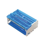
Electric Fitting Pointer Multimeter To Distinguish The Electrodes Of Junction Field Effect Tube
Two Pole Distribution Blocks pointer multimeter to identify the electrodes of junction field effect tubes:
Set the multimeter to RX1k, touch the pin assumed to be the gate G with the black test lead, and then touch the other two pins with the red test lead. If the resistance values are both relatively small (5~100), swap the red and black test leads and measure again. If the resistance values are both large (∞), it means that they are all reverse resistances (PN junction reverse), which belongs to N-channel tubes, and the pin touched by the black test lead is the gate G, and it means that the original assumption is correct. If the resistance values measured again are all very small, it means that it is a forward resistance, which belongs to a P-channel field effect tube, and the black test lead is also connected to the gate G. If the above situation does not occur, you can swap the red and black test leads and test according to the above method until the gate is determined. -Generally, the source and drain of the junction field effect tube are symmetrical during manufacturing, so when the gate G is determined, it is not necessary to identify the source S and drain D, because these two poles can be used interchangeably. The resistance between the source and the drain is several thousand ohms.

