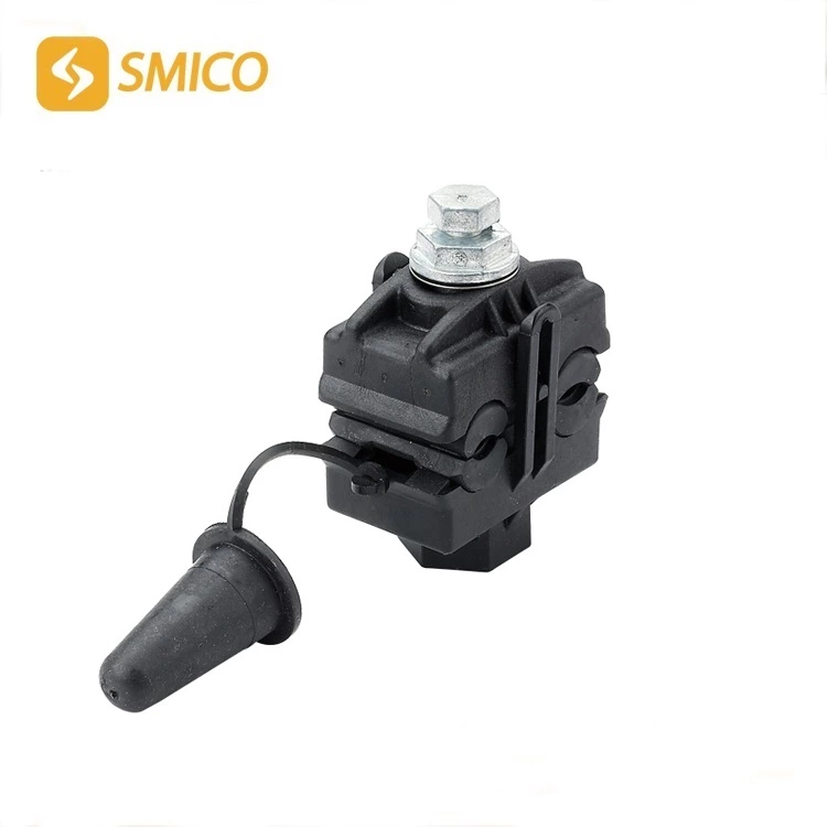
Precautions For Installing High Voltage Cable Accessories
In actual operation, there are many accidents caused by Insulation Piercing Connector accessories. According to the causes of the failure, they can be roughly divided into the following categories: manufacturer manufacturing reasons, construction quality reasons, design reasons of the design unit, and external force damage. The following is a brief introduction to the reasons for construction quality: There are many cases of high-voltage cable system failures due to construction quality. The main reasons are as follows: First, the site conditions are relatively poor. The environment and process requirements for cables and connectors are very high when they are manufactured in the factory, and the temperature, humidity, and dust at the construction site are not well controlled. Second, during the cable construction process, it is inevitable that small slip marks will be left on the insulation surface. Semi-conductive particles and sand on the emery cloth may also be embedded in the insulation. In addition, during the joint construction process, the insulation is exposed to the air, and moisture will be absorbed into the insulation. These will leave hidden dangers for long-term safe operation. Third, the installation was not strictly in accordance with the process construction or process regulations, and possible problems were not considered. Fourth, the DC withstand voltage test was used for the completion acceptance, which caused the formation of a reverse electric field in the connector, resulting in insulation damage. Fifth, it was caused by poor sealing. Serious defects caused by construction quality will generally cause failures during the completion test before commissioning or within one or two years after commissioning, while some minor problems may become hidden dangers for long-term operation. Using a professional construction team and strengthening the technical level and quality awareness of installers are important means to reduce cable accidents. The following is a brief introduction to the precautions for installing medium and low voltage cable accessories:
1. General precautions
a) Keep the installation process clean;
b) Check the moisture of the cable, especially whether the core has water ingress;
c) Strictly control the stripping size, and each stripping layer should not damage the inner layer structure;
d) The cross-section of the semi-conductive layer should be smooth and flat, and the transition with the insulation layer should be smooth;
e) After the core insulation is stripped, the inner semi-conductive layer should be cleaned and the oxide layer on the core should be polished;
f) Sharp corners and burrs should be removed after the hardware is crimped.
g) Sharp corners and burrs should be removed after the hardware is crimped.
2. Precautions for installation of heat shrink cable accessories
a) When shrinking heat shrink accessories, do not use too much fire to avoid burning the material. The flame should swing evenly in the circumferential direction and shrink forward; when shrinking the terminal gloves, shrink from the middle to both ends, when shrinking the terminal heat shrink tube, shrink from the bottom to the top, and when shrinking the middle heat shrink tube, shrink from the middle to both ends;
b) When shrinking the stress tube, the stress tube must overlap with the shielding layer, and the upper end of the stress tube should exceed the length of more than 60mm above the shielding fracture
c) When installing the connector, the stress tube should not be overlapped on the copper shielding layer, but only on the outer semi-conductive layer;
d) When installing the connector, the end of the cable insulation must be cut into a reaction force cone, and the cone surface must be smooth;
e) When installing the connector, check whether all accessories are inserted into the cable before crimping the connector.
3. Precautions for installation of cold shrink cable accessories
a) Check the cold shrink parts before installation. No cracking is allowed. Avoid sharp tools and blades from scratching the cold shrink parts.
b) Do not pull out the supporting frame of the cold shrink parts before installation.
c) After wrapping the filling glue around the fork of the multi-core terminal, wrap a layer of PVC tape on the upper part of the filling glue to prevent the filling glue from being pulled out when the frame is pulled out.
d) Strictly strip and cut according to the process size and make temporary marks. The cold shrink parts should be flush with the marks after shrinking. No longitudinal cuts should be made when cutting the cold shrink insulation tube.
e) When installing the joint, the extended end of the cold shrink part frame strip should be put into the longer end of the cable first to facilitate pulling the frame.
f) When installing the joint, the cable insulation end cannot be cut into a cone. After crimping and stretching, the center position between the two insulations should be re-determined. The process size should be measured from one end based on this center and marked.
g) Finish the semi-conductive tape wrapped around the metal shield or connecting tube well to prevent the semi-conductive tape from being pulled apart and onto the insulation when the frame is pulled out.